
本人一直都在做硬件、FPGA对驱动来说只会裸奔。。在Linux底下的驱动基本上完全不会。看了这篇文章感觉不错,就照着他的流程跑了一遍,问题还是遇到了一些,在这里记录一下。
0.测试环境
软件平台:
Vivado 2017.1
PetaLinux 2017.1
i9 7900X 神机
CentOS 7.3 虚拟机
硬件平台:
ZCU102 (ZynqMP)
ZedBoard (Zynq)
我在ZCU102和ZedBoard上都进行了测试,Zynq和ZynqMP两种都验证了一下。
1. vivado工程
新建block design,在其中添加Zynq硬核、5转1的Concat IP,
然后直接添加板子的LED到一个新的AXI GPIO IP,如下图 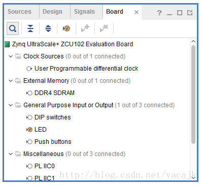
讯享网
IRQ名称 中断类型 中断号ZynqMP/Zynq pl_irq_er 上升沿中断 121 / 61 pl_irq_ef 下降沿中断 122 / 62 pl_irq_lh 高电平中断 123 / 63 pl_irq_ll 低电平中断 124 / 64 axi_gpio_0 N/A 125 / 65 讯享网
- 1
- 2
- 3
- 4
- 5
- 6
- 7
讯享网set_property PACKAGE_PIN AN13 [get_ports "pl_irq_ll"] ;# Bank 44 VCCO - VCC3V3 - IO_L2N_AD10N_44 set_property IOSTANDARD LVCMOS33 [get_ports "pl_irq_ll"] ;# Bank 44 VCCO - VCC3V3 - IO_L2N_AD10N_44 set_property PACKAGE_PIN AM14 [get_ports "pl_irq_lh"] ;# Bank 44 VCCO - VCC3V3 - IO_L2P_AD10P_44 set_property IOSTANDARD LVCMOS33 [get_ports "pl_irq_lh"] ;# Bank 44 VCCO - VCC3V3 - IO_L2P_AD10P_44 set_property PACKAGE_PIN AP14 [get_ports "pl_irq_ef"] ;# Bank 44 VCCO - VCC3V3 - IO_L1N_AD11N_44 set_property IOSTANDARD LVCMOS33 [get_ports "pl_irq_ef"] ;# Bank 44 VCCO - VCC3V3 - IO_L1N_AD11N_44 set_property PACKAGE_PIN AN14 [get_ports "pl_irq_er"] ;# Bank 44 VCCO - VCC3V3 - IO_L1P_AD11P_44 set_property IOSTANDARD LVCMOS33 [get_ports "pl_irq_er"] ;# Bank 44 VCCO - VCC3V3 - IO_L1P_AD11P_44
- 1
- 2
- 3
- 4
- 5
- 6
- 7
- 8
- 9
ZedBoard
# ---------------------------------------------------------------------------- # User DIP Switches - Bank 35 # ---------------------------------------------------------------------------- set_property PACKAGE_PIN F22 [get_ports {pl_irq_er}]; # "SW0" set_property PACKAGE_PIN G22 [get_ports {pl_irq_ef}]; # "SW1" set_property PACKAGE_PIN H22 [get_ports {pl_irq_lh}]; # "SW2" set_property PACKAGE_PIN F21 [get_ports {pl_irq_ll}]; # "SW3" #set_property PACKAGE_PIN H19 [get_ports {SW4}]; # "SW4" #set_property PACKAGE_PIN H18 [get_ports {SW5}]; # "SW5" #set_property PACKAGE_PIN H17 [get_ports {SW6}]; # "SW6" #set_property PACKAGE_PIN M15 [get_ports {SW7}]; # "SW7" # Set the bank voltage for IO Bank 35 to 1.8V by default. # set_property IOSTANDARD LVCMOS33 [get_ports -of_objects [get_iobanks 35]]; set_property IOSTANDARD LVCMOS25 [get_ports -of_objects [get_iobanks 35]]; #set_property IOSTANDARD LVCMOS18 [get_ports -of_objects [get_iobanks 35]]; - 1
- 2
- 3
- 4
- 5
- 6
- 7
- 8
- 9
- 10
- 11
- 12
- 13
- 14
- 15
- 16
- 17
在Diagram中点击下图中的Run Connection Automation,可以配置对应开发板默认的Zynq设置。 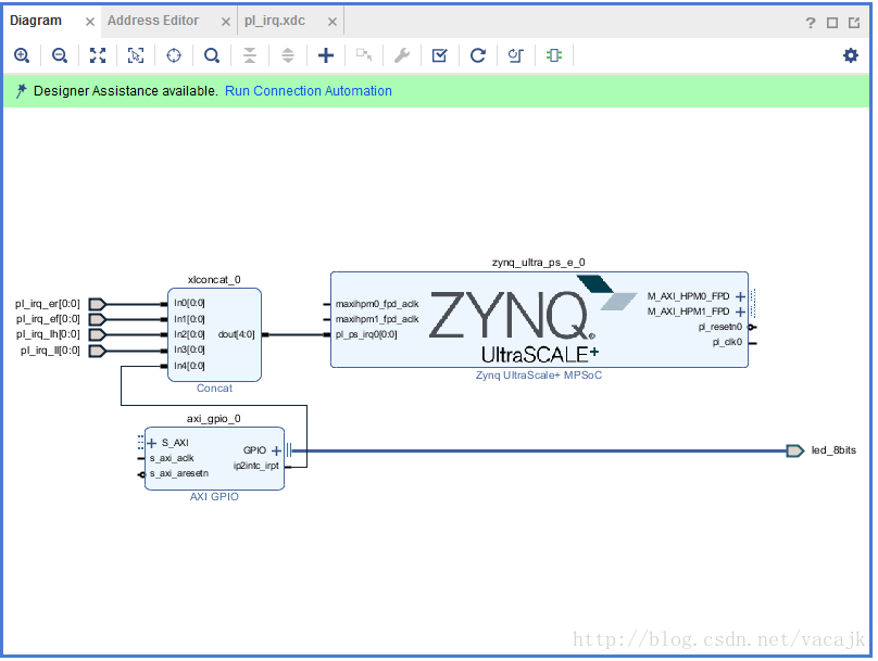
弹出界面后点击OK。
vivado将自动创建reset、interconnector的IP并进行连接
ZCU102 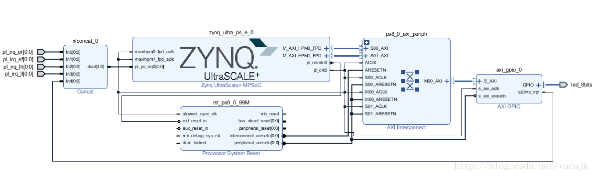
ZedBoard 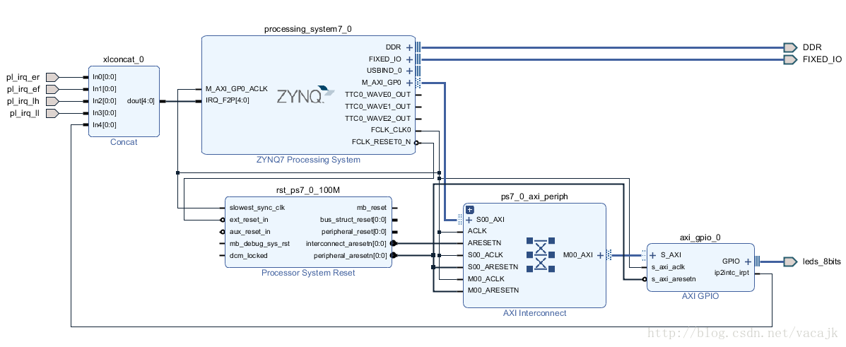
不用太关心Zynq或ZynqMP的具体配置和连接方式,我们直接使用这个工程就好了。
然后进行常规的操作
讯享网Generate Output Products Create HDL Wrapper Generate Bitstream File -> Export -> Export Hardware(Include bitstream) File -> Launch SDK
- 1
- 2
- 3
- 4
- 5
- 6
最终在工程目录下的*.sdk中生成了config_mpsoc_wrapper_hw_platform_0文件夹,里面包含了PetaLinux需要的hdf文件和FPGA配置的bit文件。
注意:到这里还没有结束,下面的步骤可以防止PetaLinux编译是的错误问题。
错误描述是fsbl或pmu-firmware在PetaLinux编译时出错,我自己感觉这是软件的bug或者是我的电脑网络不太好的问题。
解决的方法自己在Xilinx SDK中独立编译fsbl和pmufw的可执行文件。(pmufw只针对ZynqMP)
在操作方式如下图,分别建立fsbl和pmufw工程,工程代码下一个界面中的templates里选择对应的即可 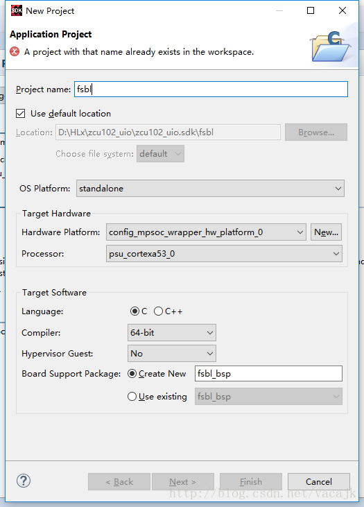
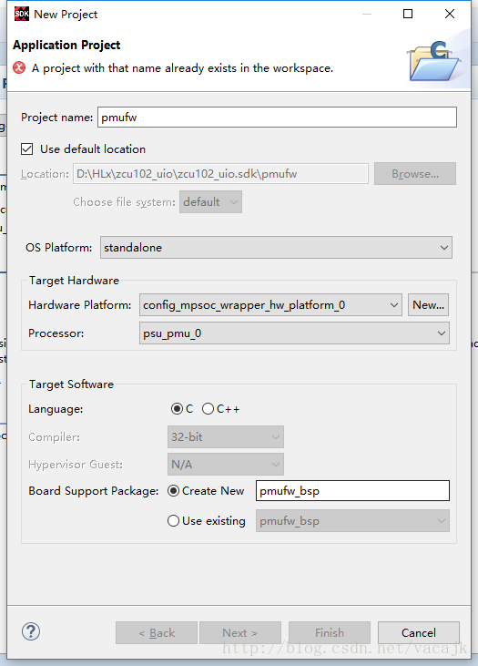
这样在.sdk/fsbl/Debug 和.sdk/pmufw/Debug中就分别得到了fsbl.elf和pmufw.elf两个可执行文件,我们在后面生成boot.bin时候需要使用到。
PetaLinux工程
$ systemctl start tftp.socket $ systemctl start tftp.service $ source /opt/pkg/petalinux/settings.sh $ petalinux-create -t project --template zynqMP -n zcu102-pl2ps_irq $ cd zcu102-pl2ps_irq/ $ petalinux-config --get-hw-description ../config_mpsoc_wrapper_hw_platform_0/ - 1
- 2
- 3
- 4
- 5
- 6
- 7
在petalinux-config中取消fsbl和pmufw的编译,取消它们的勾选 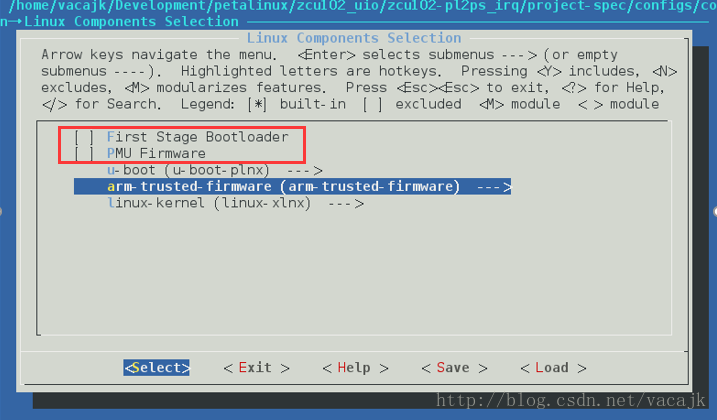
保存并退出petalinux-config。
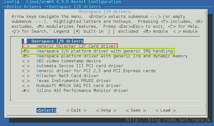
配置kernel打开UIO中断的支持
讯享网$ petalinux-config -c kernel Device Drivers ---> Userspace I/O drivers ---> < > generic Hilscher CIF Card driver <M> Userspace I/O platform driver with generic IRQ handling
- 1
- 2
- 3
- 4
- 5
- 6
编译出设备树文件
$ petalinux-build -c device-tree - 1
- 2
中间有可能出现错误,一种情况是缺少libstdc++和glibc-devel,使用下面命令安装
讯享网yum install libstdc++.i686 yum install glibc-devel.i686
- 1
- 2
- 3
还有一种情况就是在上面Vivado工程中提到的我们需要自己生成fsbl和pmufw文件,否则有时候会错误。当然我们刚才在petalinux-config中已经取消了它们的编译,这里应该不会出现这种情况。
在文件./components/plnx_workspace/device-tree-generation/pl.dtsi 中可以查看PL侧的设备树信息,里面包含了axi_gpio_0的设备树,需要用到。
注意:
假如需要添加其他自定义设备树文件,如直接从Xilinx提供的开发板BSP中会有对应板子的dtsi文件,首先需要在system-user.dtsi中加入文本
/include/ “board-conf.dtsi”
其次需要修改./project-spec/meta-user/recipes-bsp/device-tree/device-tree-generation_%.bbappend 这个文件,加入文本
file://board-user.dtsi \
两个必须同时修改了,才有效果,否则会出错说找不到文件。

/include/ "system-conf.dtsi" / { amba_pl@0 { #address-cells = <2>; #size-cells = <2>; compatible = "simple-bus"; ranges ; gpio@a0000000 { #gpio-cells = <2>; #interrupt-cells = <2>; compatible = "generic-uio"; gpio-controller ; interrupt-controller ; interrupt-parent = <&gic>; interrupts = <0 93 4>; reg = <0x0 0xa0000000 0x0 0x10000>; xlnx,all-inputs = <0x0>; xlnx,all-inputs-2 = <0x0>; xlnx,all-outputs = <0x1>; xlnx,all-outputs-2 = <0x0>; xlnx,dout-default = <0x00000000>; xlnx,dout-default-2 = <0x00000000>; xlnx,gpio-width = <0x8>; xlnx,gpio2-width = <0x20>; xlnx,interrupt-present = <0x1>; xlnx,is-dual = <0x0>; xlnx,tri-default = <0xFFFFFFFF>; xlnx,tri-default-2 = <0xFFFFFFFF>; }; uio@0 { compatible = "generic-uio"; status = "okay"; interrupt-controller; interrupt-parent = <&gic>; interrupts = <0 89 1>; }; uio@1 { compatible = "generic-uio"; status = "okay"; interrupt-controller; interrupt-parent = <&gic>; interrupts = <0 90 2>; }; uio@2 { compatible = "generic-uio"; status = "okay"; interrupt-controller; interrupt-parent = <&gic>; interrupts = <0 91 4>; }; uio@3 { compatible = "generic-uio"; status = "okay"; interrupt-controller; interrupt-parent = <&gic>; interrupts = <0 92 8>; }; }; chosen { bootargs = "earlycon clk_ignore_unused uio_pdrv_genirq.of_id=generic-uio"; stdout-path = "serial0:n8"; }; }; &uart1 { status = "disabled"; }; - 1
- 2
- 3
- 4
- 5
- 6
- 7
- 8
- 9
- 10
- 11
- 12
- 13
- 14
- 15
- 16
- 17
- 18
- 19
- 20
- 21
- 22
- 23
- 24
- 25
- 26
- 27
- 28
- 29
- 30
- 31
- 32
- 33
- 34
- 35
- 36
- 37
- 38
- 39
- 40
- 41
- 42
- 43
- 44
- 45
- 46
- 47
- 48
- 49
- 50
- 51
- 52
- 53
- 54
- 55
- 56
- 57
- 58
- 59
- 60
- 61
- 62
- 63
- 64
- 65
- 66
- 67
- 68
- 69
- 70
- 71
- 72
- 73
- 74
ZedBoard
讯享网/include/ "system-conf.dtsi" / { amba_pl { #address-cells = <1>; #size-cells = <1>; compatible = "simple-bus"; ranges ; gpio@ { #gpio-cells = <2>; #interrupt-cells = <2>; compatible = "generic-uio"; gpio-controller ; interrupt-controller ; interrupt-parent = <&intc>; interrupts = <0 33 4>; reg = <0x 0x10000>; xlnx,all-inputs = <0x0>; xlnx,all-inputs-2 = <0x0>; xlnx,all-outputs = <0x1>; xlnx,all-outputs-2 = <0x0>; xlnx,dout-default = <0x00000000>; xlnx,dout-default-2 = <0x00000000>; xlnx,gpio-width = <0x8>; xlnx,gpio2-width = <0x20>; xlnx,interrupt-present = <0x1>; xlnx,is-dual = <0x0>; xlnx,tri-default = <0xFFFFFFFF>; xlnx,tri-default-2 = <0xFFFFFFFF>; }; uio@0 { compatible = "generic-uio"; status = "okay"; interrupt-controller; interrupt-parent = <&intc>; interrupts = <0 29 1>; }; uio@1 { compatible = "generic-uio"; status = "okay"; interrupt-controller; interrupt-parent = <&intc>; interrupts = <0 30 2>; }; uio@2 { compatible = "generic-uio"; status = "okay"; interrupt-controller; interrupt-parent = <&intc>; interrupts = <0 31 4>; }; uio@3 { compatible = "generic-uio"; status = "okay"; interrupt-controller; interrupt-parent = <&intc>; interrupts = <0 32 8>; }; }; chosen { bootargs = "console=ttyPS0, earlyprintk uio_pdrv_genirq.of_id=generic-uio"; stdout-path = "serial0:n8"; }; };
- 1
- 2
- 3
- 4
- 5
- 6
- 7
- 8
- 9
- 10
- 11
- 12
- 13
- 14
- 15
- 16
- 17
- 18
- 19
- 20
- 21
- 22
- 23
- 24
- 25
- 26
- 27
- 28
- 29
- 30
- 31
- 32
- 33
- 34
- 35
- 36
- 37
- 38
- 39
- 40
- 41
- 42
- 43
- 44
- 45
- 46
- 47
- 48
- 49
- 50
- 51
- 52
- 53
- 54
- 55
- 56
- 57
- 58
- 59
- 60
- 61
- 62
- 63
- 64
- 65
- 66
- 67
- 68
- 69
- 70
- 71
两个板子的内容不太一样,跟ZynqMP和Zynq的区别有关系,在这里不用太去考虑。只考虑dtsi文件中相同的地方。
首先因为我们四个中断号都没有硬件IP,所以PetaLinux并没有在pl.dtsi中给他们生成设备树信息,所以我们需要受动添加,如
uio@0 { compatible = "generic-uio"; status = "okay"; interrupt-controller; interrupt-parent = <&intc>; interrupts = <0 29 1>; }; - 1
- 2
- 3
- 4
- 5
- 6
- 7
- 8
看amba_pl下gpio@中,跟PL.dtsi不同,将compatible的”xlnx,xps-gpio-1.00.a”改为了”generic-uio”,这样就将此axi_gpio_0改为了UIO的驱动类型。
看chosen的bootargs中增加了”uio_pdrv_genirq.of_id=generic-uio”。
ZynqMP和Zynq的一个区别需要注意,ZynqMP的interrupt-parent指向的是&gic,而Zynq指向了&intc。其实可以再看看其他的dtsi文件,可以发现,intc其实也是指向了cpu的gic,所以说实际上是一样的,并没有使用PL侧的INTC IP核中断。
ZynqMP还需要将uart1的status设置为disabled,不进行这个配置的话,系统会卡死在下面的log处
讯享网[ 0.008300] Console: colour dummy device 80x25 [ 0.012558] console [tty0] enabled [ 0.015924] bootconsole [cdns0] disabled
- 1
- 2
- 3
- 4
将uart1 disabled掉就可以正常启动了。具体原因不太清楚,在这里就先这样处理了。在ug1209中的说明也中关闭了uart1。
下面就可以进行编译了
$ petalinux-build - 1
- 2
讯享网//对于Zynq $ petalinux-package --boot --fsbl=./images/linux/fsbl.elf --fpga --u-boot --force //对于ZynqMP $ petalinux-package --boot --fsbl=./images/linux/fsbl.elf --fpga --atf --pmufw --u-boot //保存pre-built $ petalinux-package --prebuilt --fpga ./images/linux/zed_video_wrapper.bit --force
- 1
- 2
- 3
- 4
- 5
- 6
- 7
- 8
将/images/linux目录下的boot.bin和image.ub复制到SD卡上,插到ZCU102上,启动板子。
输入用户名root,密码root
查看uio设备是否正常 
发现少了两个uio
看前面的系统log,发现下降沿触发和低电平触发中断不可用,SW1和SW3不能用 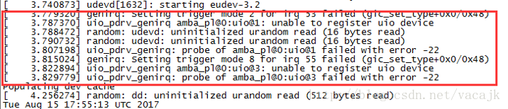
只有AXI GPIO,SW0,SW2的中断可用 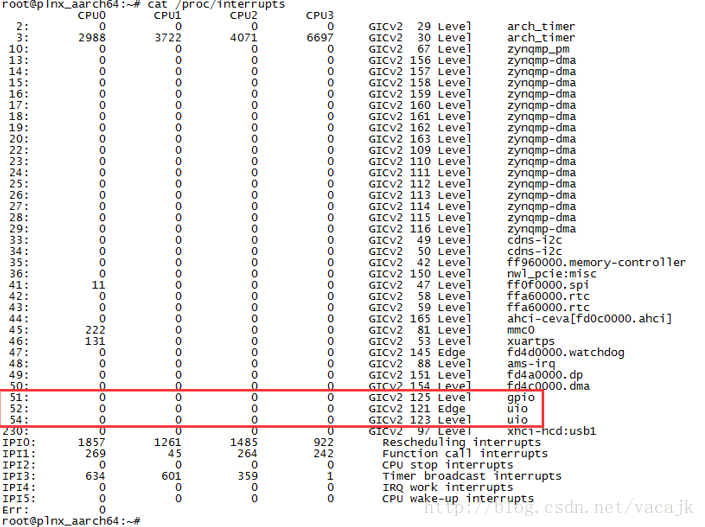
向上拨动SW0和SW2 
可以查看内核中的源码uio_pdrv_genirq.c和介绍https://01.org/linuxgraphics/gfx-docs/drm/driver-api/uio-howto.html 
何晔老师写到
在结合驱动代码./drviver/uio/uio_pdrv_genirq.c)可知,每个UIO设备会有对应的/dev/uioX的设备节点。用户态驱动程序的读操作会阻塞直到UIO硬件中断发生。UIO的中断处理程序uio_pdrv_denirq_handler()会关闭该硬件中断。用户态驱动程序需要通过write函数来触发uio_pdrv_genirq_irqcontrol()以完成中断的使能和关闭。
使用echo 0x1 > /dev/uio1来写入,重新开启uio中断。 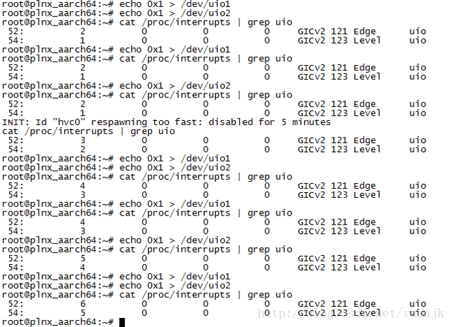
从何老师那里拷贝过来了两个测试代码,pin-uio-test.c和gpio-uio-test.c。对gpio-uio-test.c进行了修改,看了看LED灯的测试。
pin-uio-test.c
/* * This application reads/writes GPIO devices with UIO. * */ #include <stdio.h> #include <stdlib.h> #include <unistd.h> #include <sys/mman.h> #include <sys/types.h> #include <sys/stat.h> #include <fcntl.h> #include <errno.h> void usage(void) { printf("*argv[0] -d <UIO_DEV_FILE>\n"); printf(" -d UIO device file. e.g. /dev/uio0"); return; } int main(int argc, char *argv[]) { int c; int fd; char *uiod; unsigned i = 0; unsigned icount; int irq_on = 1; int err; printf("pin UIO test.\n"); while((c = getopt(argc, argv, "d:io:h")) != -1) { switch(c) { case 'd': uiod=optarg; break; case 'h': usage(); return 0; default: printf("invalid option: %c\n", (char)c); usage(); return -1; } } /* Open the UIO device file */ fd = open(uiod, O_RDWR); if (fd < 1) { perror(argv[0]); printf("Invalid UIO device file:%s.\n", uiod); usage(); return -1; } for(i = 0; ; ++i) { /* Print out a message, for debugging. */ if (i == 0) fprintf(stderr, "Started uio test driver.\n"); else fprintf(stderr, "Interrupts: %d\n", icount); /* enable IRQ, trigger the irqcontrol of driver */ write(fd, &irq_on, sizeof(irq_on)); /* Here we got an interrupt from the device. Do something to it. */ err = read(fd, &icount, 4); if (err != 4) { perror("uio read:"); break; } } return 0; } - 1
- 2
- 3
- 4
- 5
- 6
- 7
- 8
- 9
- 10
- 11
- 12
- 13
- 14
- 15
- 16
- 17
- 18
- 19
- 20
- 21
- 22
- 23
- 24
- 25
- 26
- 27
- 28
- 29
- 30
- 31
- 32
- 33
- 34
- 35
- 36
- 37
- 38
- 39
- 40
- 41
- 42
- 43
- 44
- 45
- 46
- 47
- 48
- 49
- 50
- 51
- 52
- 53
- 54
- 55
- 56
- 57
- 58
- 59
- 60
- 61
- 62
- 63
- 64
- 65
- 66
- 67
- 68
- 69
- 70
- 71
- 72
- 73
- 74
- 75
- 76
- 77
gpio-uio-test.c
讯享网/* * This application reads/writes GPIO devices with UIO. * */ #include <stdio.h> #include <stdlib.h> #include <unistd.h> #include <sys/mman.h> #include <fcntl.h> #define IN 0 #define OUT 1 #define GPIO_MAP_SIZE 0x10000 #define GPIO_DATA_OFFSET 0x00 #define GPIO_TRI_OFFSET 0x04 #define GPIO2_DATA_OFFSET 0x08 #define GPIO2_TRI_OFFSET 0x0C #define GIER 0x011C #define IP_IER 0x0128 #define IP_ISR 0x0120 void usage(void) { printf("*argv[0] -d <UIO_DEV_FILE> -i|-o <VALUE>\n"); printf(" -d UIO device file. e.g. /dev/uio0"); printf(" -i Input from GPIO\n"); printf(" -o <VALUE> Output to GPIO\n"); return; } int main(int argc, char *argv[]) { int c; int fd; int direction=IN; char *uiod; int value = 0; int valued = 0; int irq_on = 1; void *ptr; printf("GPIO UIO test.\n"); while((c = getopt(argc, argv, "d:io:h")) != -1) { switch(c) { case 'd': uiod=optarg; break; case 'i': direction=IN; break; case 'o': direction=OUT; valued=atoi(optarg); break; case 'h': usage(); return 0; default: printf("invalid option: %c\n", (char)c); usage(); return -1; } } /* Open the UIO device file */ fd = open(uiod, O_RDWR); if (fd < 1) { perror(argv[0]); printf("Invalid UIO device file:%s.\n", uiod); usage(); return -1; } /* mmap the UIO device */ ptr = mmap(NULL, GPIO_MAP_SIZE, PROT_READ|PROT_WRITE, MAP_SHARED, fd, 0); /* Print Interrupt Registers */ value = *((unsigned *) (ptr + GIER)); printf("%s: GIER: %08x\n",argv[0], value); value = *((unsigned *) (ptr + IP_IER)); printf("%s: IP_IER: %08x\n",argv[0], value); value = *((unsigned *) (ptr + IP_ISR)); printf("%s: IP_ISR: %08x\n",argv[0], value); /* Enable All Interrupts */ printf("%s: Enable All Interrupts in Regs\n", argv[0]); *((unsigned *)(ptr + GIER)) = 0x; *((unsigned *)(ptr + IP_IER)) = 0x3; *((unsigned *)(ptr + IP_ISR)) = 0x3; /* Enable UIO interrupt */ write(fd, &irq_on, sizeof(irq_on)); if (direction == IN) { /* Read from GPIO */ *((unsigned *)(ptr + GPIO_TRI_OFFSET)) = 255; value = *((unsigned *) (ptr + GPIO_DATA_OFFSET)); printf("%s: input: %08x\n",argv[0], value); } else { /* Write to GPIO */ *((unsigned *)(ptr + GPIO_TRI_OFFSET)) = 0; value = valued; *((unsigned *)(ptr + GPIO_DATA_OFFSET)) = value; } /* Print Interrupt Registers */ value = *((unsigned *) (ptr + GIER)); printf("%s: GIER: %08x\n",argv[0], value); value = *((unsigned *) (ptr + IP_IER)); printf("%s: IP_IER: %08x\n",argv[0], value); value = *((unsigned *) (ptr + IP_ISR)); printf("%s: IP_ISR: %08x\n",argv[0], value); munmap(ptr, GPIO_MAP_SIZE); return 0; }
- 1
- 2
- 3
- 4
- 5
- 6
- 7
- 8
- 9
- 10
- 11
- 12
- 13
- 14
- 15
- 16
- 17
- 18
- 19
- 20
- 21
- 22
- 23
- 24
- 25
- 26
- 27
- 28
- 29
- 30
- 31
- 32
- 33
- 34
- 35
- 36
- 37
- 38
- 39
- 40
- 41
- 42
- 43
- 44
- 45
- 46
- 47
- 48
- 49
- 50
- 51
- 52
- 53
- 54
- 55
- 56
- 57
- 58
- 59
- 60
- 61
- 62
- 63
- 64
- 65
- 66
- 67
- 68
- 69
- 70
- 71
- 72
- 73
- 74
- 75
- 76
- 77
- 78
- 79
- 80
- 81
- 82
- 83
- 84
- 85
- 86
- 87
- 88
- 89
- 90
- 91
- 92
- 93
- 94
- 95
- 96
- 97
- 98
- 99
- 100
- 101
- 102
- 103
- 104
- 105
- 106
- 107
- 108
- 109
- 110
- 111
- 112
- 113
- 114
- 115
- 116
- 117
- 118
- 119
- 120
- 121
- 122
- 123
在虚拟机中编译
$ aarch64-linux-gnu-gcc pin-uio-test.c -o pin-uio-test $ aarch64-linux-gnu-gcc gpio-uio-test.c -o gpio-uio-test - 1
- 2
- 3
在ZCU102中测试,并拨开关和观察LED。 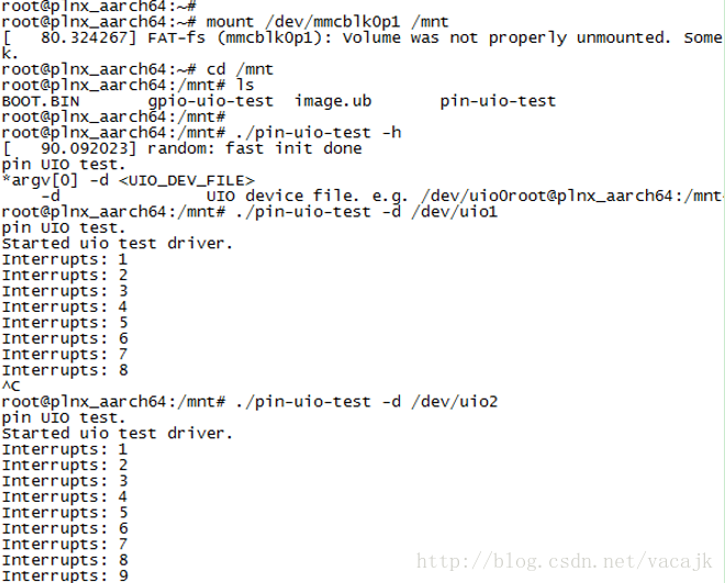
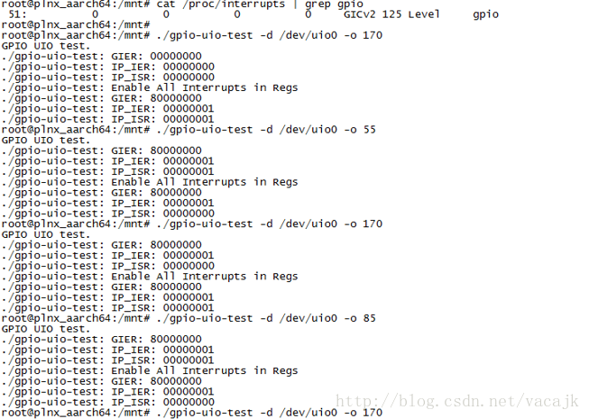
因为开关没有滤波,容易震荡产生多次中断。
实验结论
参考何老师的例子,学习了UIO外设驱动和中断的操作,对Linux驱动有了一些了解。同时测试了ZynqMp和Zynq器件,还解决了一些bug问题。
之后准备将我裸机的代码使用UIO来进行移植,因为像VDMA,Video Frame Buffer Write/Read,Video Mixer这些IP在内核中的驱动太复杂了,我搞不明白,还是直接操作寄存器来的方便些。毕竟我的系统不是很复杂的,裸机程序使用UIO来移植到Linux中还是相对简单的。
版权声明:本文内容由互联网用户自发贡献,该文观点仅代表作者本人。本站仅提供信息存储空间服务,不拥有所有权,不承担相关法律责任。如发现本站有涉嫌侵权/违法违规的内容,请联系我们,一经查实,本站将立刻删除。
如需转载请保留出处:https://51itzy.com/kjqy/15002.html